
Key takeaways
- Name the damage correctly first: wear, scuffing, micropitting, pitting, case crushing, tooth root fatigue and overload breakage have different causes and remedies.
- Most gear failures trace back to lubrication, misalignment, overload, contamination or an inadequate material and heat treatment.
- Before cleaning or discarding a failed gear, photograph it, keep the fragments, take an oil sample and record operating data.
- Replacing a failed gear without correcting the root cause usually leads to the same failure on the new part.
Why naming the failure mode matters
A broken tooth or a pitted flank is a symptom; the cause lies elsewhere — in the lubrication, alignment, load, material or manufacture. Each damage mode develops by a different mechanism and points to a different set of causes. Using common terminology helps maintenance teams, gear manufacturers and lubricant suppliers to talk about the same thing. The international reference is ISO 10825-1 (wear and damage to gear teeth — nomenclature); AGMA 1010 offers an equivalent American terminology. The descriptions below follow these documents in simplified form.
Main failure modes
Wear
Gradual removal of material from the flanks. Abrasive wear caused by hard particles in the oil leaves fine scratches in the sliding direction; adhesive (mild) wear and polishing occur at low speed with thin oil films. Wear changes the tooth profile, increases backlash and noise, and can finally weaken the tooth. Typical causes: contaminated or degraded oil, low speed with insufficient viscosity, worn seals letting in dust.
Scuffing
Sudden local welding and tearing of the flank surfaces when the lubricant film collapses under high load and sliding speed. Scuffing appears as rough, matt, torn bands in the sliding direction, mostly near the tip and root of the teeth, often with discoloration. Causes: oil viscosity too low or wrong additive package (insufficient extreme-pressure properties), high oil temperature, overload, inadequate running-in, surface roughness or missing tip relief.
Micropitting
Very small surface fatigue cracks and pits, a few micrometres deep, that give the flank a matt grey, frosted appearance (often called grey staining). Micropitting is typical of case-hardened gears with thin lubricant films. It can stabilise, but it can also alter the profile and initiate pitting. Causes: thin oil film (low viscosity, high temperature, low speed), rough flanks, high contact stress, lubricants with low micropitting resistance.
Pitting
Surface fatigue producing craters visible to the naked eye, typically in the dedendum near the pitch line, where rolling and sliding combine with high contact stress. Initial pitting on through-hardened gears can stop once high spots are worn in; progressive pitting continues to grow. Causes: contact stress above the endurance limit of the material, poor load distribution (misalignment, deflection, helix errors), insufficient hardness, contaminated oil.
Spalling
Large, deep, irregular craters formed when pits coalesce or when fatigue cracks start below the surface. Spalling removes a substantial part of the flank and is often a step towards tooth breakage. Causes are those of progressive pitting, aggravated by heavy loads or inadequate case properties.
Case crushing
Subsurface fatigue of case-hardened gears, where cracks initiate at the transition between the hard case and the softer core and large pieces of the case break away. Causes: case depth too shallow for the tooth size and load, core hardness too low, overload. This is one reason why case depth and core hardness must be specified together on a drawing; see our guide on gear materials and heat treatment.
Tooth root fatigue breakage
A crack initiates in the tooth root fillet, where bending stress is highest, and grows over many load cycles until the tooth breaks. The fracture surface shows a smooth fatigue zone with beach marks and a small, rough final rupture zone. Causes: bending stress above the endurance limit, stress raisers in the root (notches, grinding steps, decarburisation, corrosion), misalignment concentrating the load at one end of the face, residual stresses from incorrect heat treatment.
Overload breakage
Brittle or ductile fracture in one or a few load cycles, with a rough, fibrous or granular fracture surface without beach marks. Causes: shock loads (jammed crushers or conveyors, sudden stops, short circuits in the motor), foreign bodies entering the mesh, or a tooth already weakened by another damage mode.
Plastic deformation
Permanent deformation of the flank or tooth without separation of material: rolling and peening (burrs at the tips), rippling and ridging (wavy patterns on the flank), indentation by foreign particles, or bent teeth. Typical for through-hardened or softer gears under heavy loads, and for any gear after a severe overload.
Root causes
Most failures combine several of the following factors:
- Lubrication: wrong viscosity or oil type, degraded or overheated oil, insufficient quantity, blocked jets, water contamination. Industrial gear oils are classified, for example, according to ISO 12925-1.
- Misalignment: housing deflection, worn bearings, incorrect assembly, foundation settlement or thermal distortion, giving edge loading at one end of the face width.
- Overload and shocks: process upsets, frequent starts, reversing operation, underestimated application factor.
- Contamination: dust, process material, water and wear particles entering through seals and breathers.
- Material and heat treatment: wrong steel grade, insufficient hardness, case depth too shallow or too deep, decarburisation, grinding burns, unfavourable residual stresses.
- Material defects: inclusions, segregation, forging defects, quench cracks.
- Manufacturing errors: profile and helix deviations, inadequate root fillet, poor surface finish, wrong backlash.
- Design: insufficient safety factors for the real load, missing profile or helix modifications.
How to recognise them: what to look at
- Location on the flank: near the pitch line (pitting), tip and root (scuffing), one end of the face width (misalignment), whole flank (wear, micropitting).
- Surface appearance: scratches (abrasion), matt grey (micropitting), torn bands (scuffing), craters (pitting, spalling).
- Fracture surface: beach marks and a small final zone (fatigue) or a rough surface without marks (overload).
- Contact pattern: a marking compound test on the mating gear shows load distribution.
- Both gears and the bearings: damage on one part is often the consequence of a problem on another.
Data to collect after a failure
- Photographs of the damage before cleaning, with a scale, and of the mating gear and bearings.
- All fragments, kept dry and protected, without matching or rubbing fracture surfaces.
- An oil sample from the sump and, if possible, the filter and magnetic plug deposits.
- Nameplate data and the gearbox history: operating hours, previous repairs, oil changes.
- Operating data: power, speed, load profile, starts per day, and the events just before the failure.
- Where needed, laboratory examination: hardness profile, case depth, microstructure, chemical analysis, fractography.
Mode, appearance, cause and corrective action
| Failure mode | Appearance | Typical cause | Corrective action |
|---|---|---|---|
| Abrasive wear | Fine scratches in sliding direction | Contaminated oil, worn seals | Filtration, sealing, oil change intervals |
| Scuffing | Rough, torn bands at tip and root | Oil film breakdown, overload, high temperature | Higher viscosity or EP oil, cooling, tip relief, careful running-in |
| Micropitting | Matt grey flanks | Thin oil film, rough surfaces | Smoother ground flanks, suitable oil, profile modifications |
| Pitting | Craters near pitch line | Contact stress, poor load distribution | Correct alignment, harder or case-hardened flanks, helix modification |
| Spalling | Large deep craters | Progressive pitting, heavy load | Replace gear set; review design and material |
| Case crushing | Case flaking from subsurface cracks | Case too shallow, low core hardness | Specify adequate case depth and core hardness |
| Tooth root fatigue | Root crack, beach marks | Bending overstress, root notches, misalignment | Root fillet design, shot peening, quality of heat treatment, alignment |
| Overload breakage | Rough fracture, no beach marks | Shock load, foreign body | Overload protection, process control, verify application factor |
| Plastic deformation | Rippling, ridges, burrs | Heavy load on soft flanks | Harder material or heat treatment, load review |
Prevention
- Select the oil according to the gear manufacturer’s recommendation and actual operating temperature; monitor it by regular analysis.
- Check alignment after installation and periodically; verify the contact pattern after any repair.
- Keep seals and breathers in good condition to exclude dust and water.
- Trend vibration and temperature to detect changes early.
- Specify material, heat treatment, case depth, core hardness and accuracy class on every replacement gear drawing.
- Analyse each failure and correct the cause before installing the new part.
How TSIRIKOS can help
TSIRIKOS manufactures replacement industrial gears to drawing or sample, with in-house heat treatment and gear grinding, and repairs gearboxes whose gears have failed. When a gearbox needs more than a new gear, see our gearbox repair and overhaul service and the guide on gearbox repair or replacement.
Send photos of the damage, the gearbox data and your operating conditions through the request for quotation page.
Technical FAQ
Is pitting always a reason to replace a gear?
No. Initial pitting on through-hardened gears can stop once the high spots are worn in. Progressive pitting that grows in size and number, or any pitting on case-hardened gears, should be monitored closely and usually leads to replacement before it turns into spalling or tooth breakage.
What is the difference between micropitting and pitting?
Micropitting consists of very small surface cracks and pits, a few micrometres deep, that give the flank a matt grey appearance. Pitting produces craters visible to the naked eye, typically originating near the pitch line. Micropitting can progress into pitting, but its main causes (thin lubricant film, roughness) differ.
Can TSIRIKOS examine a failed gear?
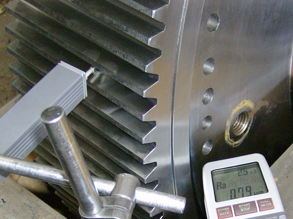
During repair work the damaged parts are examined, and the quality control department carries out dimensional inspection, crack detection, hardness measurement and roughness measurement. These checks help to identify the damage mode and to specify a suitable replacement.
Can the replacement gear be more durable than the original?
Often yes. Depending on the root cause, a replacement can be made in a better steel, case-hardened and ground, with flank modifications or a different accuracy class. The mating gear, bearings, alignment and lubrication must be checked as well, otherwise the improvement is lost.
Which data should I send with a failed gear?
Photos of the damage before cleaning, the fragments, an oil sample or analysis report, the gearbox nameplate data, operating hours, load and speed, lubrication details and any recent events such as overloads, blocked conveyors or lubrication incidents.